Kevin Cuzner's Personal Blog
Electronics, Embedded Systems, and Software are my breakfast, lunch, and dinner.
Weekend Project: Smoke Bombs

Saltpeter or KNO3
I am not in any way responsible for injury or damage resulting from this blog entry. Do not assume that these instructions are either complete or correct. Don't be stupid either; if you can't handle fire safely then you surely can't handle this safely.
Lately I have been doing small weekend projects which are generally cheap and fun. This past weekend's project, in honor of the 4th, was making smoke bombs. I found out from a friend at work that there was a store in milwaukee which sold lab supplies, including KNO3 (saltpeter). I have been wondering how to aquire that chemical since I first read the anarchist's cookbook a few years ago. It is the main ingredient in many pyrotechnical compounds including gun powder, flash powder, and smoke bombs. So, I went to this store (Laabs, Inc.) in Milwaukee, near 30th and Wisconsin and bought two pounds of this chemical @ $7.12/lb. I got carded before I could buy it, so it is an over 18 sort of substance. It looks kind of like the rouded kind of rock salt that you can buy for water softeners.
The next ingredient was easy to get: brown sugar. I got the light brown kind, but apparently the dark brown kind works better. It cost me $1.89 at Pick'n'save (so far we are up to ~$18 on this project). Now that I have introduced the main ingredients, here is the illistrated tutorial:
Materials
Saltpeter or KNO3. It doesn't matter which since they are the same thing.

Sugar

Postal Scale
Brown sugar. Dark brown is best, but white and light brown will also work just not as well.
A scale of some kind. I used a postage scale.
A mortar and pestle-like device. I used a baby food jar and a small piece of floor molding...anything will work as long as it isn't made of metal. It isn't like we have sparks to worry about like if we were making flash powder, but I think not using sparking materials would be a good habit to get into.
Paper towels
Rubbing alcohol

Makeshift morter & pestle
Something to put it on. This has to be able to withstand rather high temperatures and it will be stained black. I originally used 4 layers of aluminum foil on our driveway until I realized that a single smoke bomb was melting straight through the 4 layers down to the driveway. I used a flowerpot for the video at the end (it did crack). Sand also works since you can just bury it when you are done.
A lighter
Instructions
Weigh out the saltpeter and place it into the mortar. It is best to weigh it while it is inside the mortar so that it doesn't get all over the place from dumping into the mortar. Since this mixture is going to be 3 parts KNO3 to 2 parts sugar, it is easiest to make this a number divisible by 3. In this tutorial I used 48g of saltpeter.

All the measured ingredients

Mixing the sugar and saltpeter
On a paper towel, weigh out the sugar. With 48g of saltpeter I had to weigh out 24g of sugar.
Smash the saltpeter in the mortar until it is a relatively fine powder. Do not breathe the powder since saltpeter can cause medical issues including lung irritation and impotence (yes, I said impotence).
After removing the sugar from the scale, place it on a hard surface and pour the saltpeter onto the paper towel. Mix them throughly.
After mixing, fold the paper towel over the mixture to make a packet.

Packed into a paper towel
Place the packet onto a surface to light it on and put a bit of rubbing alcohol over it. It helps to make a "fuse" out of another paper towel, soak that in alcohol, and lay it across. Make sure not to get the mixture too wet since it isn't nearly as potent when it is wet.
Light the alcohol. After a few seconds there should be a hissing noise and then smoke. If the paper towel burns away during the hissing noise, the boiling greenish mixture may be observed, but be careful not to get too close. The splatter from the boiling stuff does hurt (it is quite hot) and the smoke isn't too good to breathe in.
Video and Pictures

Before lighting it

After lighting it
Ghetto Chronometer
For once, I did something simple. I have always wanted to know how fast my potato gun shoots and I have also known how to find out, but I had never gotten around to actually building something to measure the speed of a moving object. I built this almost completely out of parts that are available at your local radio shack and hardware stores. The device consists of a 2" PVC pipe with two sets of infrared diodes/detectors placed in holes spaced a foot apart which are connected to a PIC microcontroller that I have programmed to act as a "stopwatch" measuring in microseconds. Once a time is captured, the value is written to EEPROM for later gathering at the computer.
The Ghetto Chronometer. It looks rather like a pipe bomb doesn't it?
Parts List
I noticed while building this that I was using parts that were originally purchased on radioshack (aside from the microcontroller) and the home depot/ace hardware. Here is the list of parts with a few prices:
- Infrared Emitter/Detector sets ($3.49, radioshack)
- 330Ω 1/4W resistors ( $0.02 apiece if you get the 500 piece resistor set, otherwise $0.20 apiece in the 5-pack; radioshack). This value can be fudged just about anywhere as long as it doesn't drop below 90Ω or so. The lower the value, the more chance of breaking the infrared emitters. The higher the value, the less light the emitters give off (which increases the chance for noise). Use the values on the back of the package to calculate the exact resistor value if you want a fully bright light. I think about 37Ω or so will push 150mA through it with a ~3V drop.
- ~470Ω 1/4W resistor. This is for the yellow and green LEDs
- 5mm (T1-3/4) LEDs, yellow and green. These can be picked up at radio shack for various prices depending what package you get them in.
- solderless breadboard (what I used) or those grid pcbs (both at radioshack)
- 7805 (5V) Regulator ($1.59, radioshack)
- PIC16F628A or a BasicStamp. The Basic Stamp is available at radio shack for an exorbitant price, but the PIC can be purchased for about $3 at most parts suppliers (look on octopart.com for prices). The programmer is not included in this estimate, but I built the programmer described in the WinPic manual for less than $20 (google it). I currently use a K128 USB Programmer.
- 4.7K 1/4W resistors, same story as the 330Ω except you shouldn't adjust this one.
- >=100uF, <=500uF capacitors (radioshack again, not sure on price...depends what you get)
- 9V battery clip (radio shack. price depends on the type)
- 9V battery
- 16" of PVC pipe 1/2" larger than your current barrel size (leaves clearence for the emitter/detectors)
- Enough bushings to get the above PVC down to your barrel size for attachment (mine took two...stupid hardware store)
- A PVC connector 1/2" larger than your current barrel size for connecting the device to the bushings
Instructions
These instructions assume enough knowledge to construct a circuit on a breadboard from a schematic along with enough mechanical skill to saw and drill stuff.
Attach (I would solder them, but you can twist and tape if you like) relatively long wires to the ends of each infrared emitter and detector. There should be two of each in total. Make the wires different colors per pin on each device so that they can be distinguished later. Make a note of where each wire went on the back of the package they came in which should have an internal diagram for each part if you got it at radio shack. Twist each pair of wires together so that each device has a long twisted pair of wires coming off of it.
Heatshrink or tape each lead coming off of the emitters and detectors individually and then per device. This is so that no short circuits happen and so that the device is easier to insert and remove from the PVC.
Chronometer Schematic
Assemble the circuit per the schematic. The schematic uses the PIC microcontroller, so it will have to be modified for a basic stamp.
If you used the PIC, program the microcontroller with fps.hex in this file. I have also included the assembly listing for anyone who is interested
In the 16" length of PVC, drill two sets of holes directly across from each other 2" from either end. They should end up a foot apart.
Attach the bushings and connector to the PVC. Which ever end you attach these to is called "start" in the schematic. The projectile (potato) should travel from "start" to "stop".
Duct tape what ever you assembled the circuit on to the PVC in the fasion shown in the picture of the device above.
Insert each emitter/detector set into the holes on the PVC. They should be lined up with an emitter on one side and a detector on the other. The potato will interrupt the beam of light going between the emitter and detector.
If the device is going to be used outside, it might be good to put duct tape or electrical tape over the ends of the emitters/detectors so that no light leaks into the 16" tube. Light leakage can cause considerable interference since the lights are not modulated in any way.
Load your potato gun.
Attach this to the end of your barrel and turn it on
Fire. The green LED should light up if it caught the speed correctly, the yellow one will light up if there was an error.
Read the microcontroller's EEPROM. The time it took in microseconds for the potato to go one foot should be written in locations 0x03 and 0x04, most significant byte first. Use a hex->decimal converter to get the value, multiply it by 0.000001, and take the inverse. This is the FPS of your gun. Subsequent firings will be written in locations 0x05 & 0x06, 0x07 & 0x08, and so on. It should remember where it was last written between runs until you reprogram it or run out of space.
How it works
Overall its pretty simple: A potato interrupts the "start" beam which starts the 16-bit timer and it interrupts the "stop" beam a few microseconds later which stops the 16-bit timer. After the timer is stopped, the value of the timer (which also happens to be the number of microseconds between the start and stop pulses) is written to the internal EEPROM at the address specified in location 0x00. The green LED is then turned on and the microcontroller wants for the next "start" interruption. If there is an error (like the EEPROM not being able to write or the timer overflowing), the yellow LED lights up and the microcontroller waits for the next start pulse.
The microcontroller runs on the internal oscillator which gives 1MIPS. The 16-bit timer is connected to the internal oscillator with no prescaler so that it increments every microsecond (1MIPS = 0.000001 per instruction) when the timer is turned on. Since it is a 16-bit timer, it can time a maximum of 65535 microseconds or 0.065535 seconds. This gives a minimum speed of 15.26fps and a maximum speed of 1,000,000fps. I guess this could be used on a rifle, but I am pretty sure the emitter/detector pairs would have to be switched out with something with less lag time.
To test to see if the infrared emitters are even working try looking at them through a digital camera. A digital camera has better eyes than we do, so it can see infrared as a whitish/purpleish light. The emitters are rather narrow beam, so they will have to be pointing right at the camera to be visible. Oh, and if any part of this heats up, thats bad. Nothing on this should generate much heat, including the regulator. The whole thing should draw about 50mA with the parts listed above.
Things to add
Obviously, there are some things that could be done with this to make it even cooler. Some of my ideas:
- Add an LCD screen that shows the milliseconds it took (or even fps)
- Store the value in feet per second instead of milliseconds. I would have done this in the first plac, but I don't feel like finding out how to do division like that in assembler.
- Add a serial interface so that it can hook up to a computer and report its findings. I was originally going to do this, but I didn't have enough 0.1uF capacitors for my MAX232 chip.
- Something to prevent the wires coming off of the emitters/detectors from getting bent if the gun roles around.
- ...
Ubuntu 9.04
I have just installed Ubuntu 9.04 Netbook Remix on my Acer Aspire One and I have to say it is pretty awesome. First of all, it really does boot in 30 seconds. It took 28 seconds to get to the login screen which is most of the booting. From there it was just the normal login stuff, so it was very fast. Secondly, the Suspend/Resume is also very fast. Fast fast fast. That seems to be the point of this distro. Anyway, I'm definitely keeping this one on my computer.
Ubuntu 9.04 Netbook Remix
Eureka! The Dot Matrix Displays Work!

Running one display block with pixel 0,0 turned off
I have finally managed to get a dot matrix display running full bore without resorting to outrageous voltages such as 18V on 5V logic. I have been working towards this moment for probably 2 or 3 years now.
This uses a pinned version of the hardware described in previous posts and more or less proves that it will work with that hardware with few modifications. The only major difference is that I am not using the same chip for the LED current sink. In the picture on the right it is running at an input voltage of 6.37V@325mA which is regulated down to 5.26V and 4.78V.
One major deviation from the hardware mentioned previously is that the row decoder is running at a slightly higher voltage than the rest of the circuit (5.26V). This is to remedy a problem I noticed with the MOSFETs in which their gates are not fully turned on unless the gate voltage is above the drain voltage. What I ended up doing was running a 5.1V zener off of the input from my power supply to create a higher voltage than the 7805 supplies to the rest of the circuit (including the MOSFETs). This is marvelously ineffecient and seems to be causing the 7805 to heat up, but that also might be from the problem that I will go over next.
The other major deviation is how I am running the column sink driver. I ordered one that I thought was almost the exact same as the one I planned to use on the PCB, but doesn't behave like the datasheet says it should. I ended up having to take away the external resistor and replace it with a direct short to ground. This effectively removed the current cap and now the chip is drawing 120mA by itself (which is bad). In contrast, the chip draws 20mA with a 300Ω resistor, but half of the rows get turned off. This in itself makes no sense since this is the column sink and for something like this to happen it would have to have something to do with the row drivers (i.e. the MOSFETs and accompanying logic), but it consistently shows up when I put a resistor on the resistor pin of the column sink chip. However, if a row starts flickering irregularly all I have to do is increase the input voltage a bit and it goes away. Any ideas as to why this would happen are appreciated (leave a comment).
From a coding standpoint I think I grossly overestimated how hard it would be to strobe this display. The chip is running at 12MIPS and so far is able to render an entire 40x16 buffer at 30fps with a ton of idle time. I have not yet implemented the grayscale dimming functionality, but even that won't add much to the overhead. Looking at my scope I can see that out of the 584uS between rows only ~290uS is actually used for writing to the column sink and switching which row is turned on. This means that my "processor usage" slightly less than 50%. I was expecting it to be significantly more, but now I see that implementing the 8-bit parallel bus which will be the link between this and the "computer" board will be easier than I'd hoped.
The MCC18 built-in libraries
They suck. While waiting for my parts for the clock to come in I have been trying to get my WirelessUSB transmitter to communicate through the USART properly. I ended up discovering that it was having trouble syncing with the start and stop bits and was giving me a bunch of frame errors when receiving, but it had no problem transmitting. I was absolutely puzzled as to why this was happening and I asked around a few forums to see if anyone could shed some light on the subject. One forum (I can't remember which one) said I should try controlling the USART "manually" without using the MCC18 libraries. To my great astonishment, it started echoing back and reading my characters properly without throwing any errors. Obviously, the MCC18 libraries don't work right. I have had similar problems with the MSSP libraries, but I was unable to manually control it at the time because of my lack of experience with it (I could do it now). Basically, I now say: DON'T USE THE MCC18 LIBRARIES
Revision two
After looking at my design of a few days back I decided it definately needed another revision. For one thing, I switced out the serial->parallel chips to a more common chip that I can get off of digikey (497-5746-1-ND) for $3.30 apiece which isn't too bad (it's not the best though...but it will save on shipping). I also got rid of most of that empty space that I was not using and managed to compress the entire thing so that it is as small as it can get unless I drastically change my design.
Dot Matrix revision 2
Major Changes
As you yan see I have moved all of the chips underneath the displays. I had not done this before because I thought the autorouter wouldn't be able to handle it and I would be left with 100 airwires to resolve. However, when I upgraded the chips the package size had to go up from SSOP to SOIC. This drastically reduced the complexity of routing and made it possible to fit everything beneath the displays. I was a bit sad about this change, but I could only find SOIC versions of the more popular chip (I enjoy soldering small chips because of bragging rights).
Another major change is the position of the mosfets. I have moved them from more or less a column into two "blocks" which are more or less symetrical. I had never thought of this before and it made the airwire ratnest much less dense in the long run with being able to position the column sink chips underneath the adjacent dot matrix module. The mosfets I am using are BSS138LT1GOSDKR-ND (say that 5 times fast) and are $0.58 apiece for 20 (they only way I could find them was on digireel, so the price changes with quantity).
The final major change was an error correction. I found that I had accidentally named all of my clock lines CLK. I have probably 4 different clocks and they were all connected together. I had to separate them and that pretty much broke the last design since I didn't feel like layout out the board in exactly that pattern again.
Releasing my designs
I have decided that I am going to publicize my designs if anyone wants them. However, I will not be giving out the eagle files for my own reasons. Eventually I will export the schematic in JPG (I have to clean it up a bit) and I will include the board as gerber and excellon files. This could take time, so don't expect them for a bit.
Fabrication
I am now thinking of how to get this board fabricated. I have found one company, olimex, who will do it for around $40 per board (no minimum quantity) which is really quite cheap. The also allow panelizing and will cut your boards for you if you want, so I might wait until I have the entire clock finished before sending it off for fabbing. The only problem so far is that my board is .3" too wide for their smaller double sided panel. The upgrade is over $100 and adds about 6" on every side to the space which I don't need unless I decided to make two clocks and panelize all the parts into one board. Hopefully it isn't too hard to get these fabricated since I kind of need them to be fabricated before I can do serious testing on my software.
Resurrecting the Dot Matrix Clock
Man, I have been working on this project since probably 2006. This is by far my longest lived project with about 4 different breadboarded prototypes, 2 or 3 different control schemes, 2 differnt types of displays, and 3 different microcontrollers designed for. I think I have settled on a final design and I do have to say that this clock is more like a computer than an actual clock.
Background
A few years back I saw a POV clock made using a PIC16F84 which I thought was pretty cool. The only drawback that I saw at the time was the fact that it depended on moving parts that made noise. I really wanted to make something like that, so I looked into Dot Matrix displays. At first they seemed really expensive and difficult to get, but I eventually learned that surplus sites and eBay had very cheap displays that I could get. I proposed the idea to my mom to see if she would pay for it and she agreed (to a reasonable limit). I expected the project to take 6 months to a year. I was dead wrong. Getting a display to even be bright enough to see was a challange on its own, but eventually I learned enough about how to push LEDs to their limits that I could get a visible display running. Originally I used LPT747R displays, but these turned out to be too dim and even after pumping 18V through my 5V logic (resulting in the literal explosion of a hex inverter, but no damage to any of the other parts strangely) they were still barely visible under normal lighting. I discovered that even though LEDs may seem bright when powered constantly they are dimmed to about 1/16 of their original brightness when ran multiplexed. An added bonus of this is that you can pump about 16 times the amount of rated current through an LED (this reduces the LED life though...and if your display freezes those pixels are shot). The other brightness limiting factor is the maximum current driving capacity of the chips used to supply the current and to sink the current. Using standard 74HC logic didn't work very well since they simply couldn't supply enough current (this is probably why 18V didn't blow up the LEDs...not enough current). It took a while, but I have been able to figure out how to drive enough current through the displays to get them to be bright enough (more on this later). Recently I switched over to some 8x8 dot matrices which have also increased visibility greatly.
The display uses an array of serial->parrallel shift registers driving (now sinking) the rows with either a multiplexor or mosfet array sinking (now driving) the rows. I now use a combination of a multiplexor and mosfet array to drive the rows. The entire system is controlled by a microcontroller (originally a 16F628A, but now an 18F4550). The microcontroller stores two entire screens in memory and displays one at a time. During the displaying process each row is clocked out to a chain of shift registers and once the entire row is out the registers shift their data out to some latches which turn on specific LEDs. The rows are controlled by the microcontroller in some fashion which has varied depending on the current mockup.
The current hardware
The current version of the Dot Matrix clock consists of two main boards: The display board and the controller board. As of this writing I have only completed the PCB layouts on the display board. An 18 pin connector connects the two board. Each board has a microcontroller on it with the display board having a PIC18F4550 and the controller board having either another 18F4550 or a PIC24HJsomethingorother (I haven't decided yet). The displays are 10 8x8 displays arranged into a 5x2 pattern giving me 40x16 pixels to work with. I plan on having 4 brighness levels possible per pixel, but this depends heavily on the amount of memory I will be able to spare for display buffers on the microcontroller. The displays are column-cathode, row-anode so power is supplied to the rows.
The PCB layout as it stands now (and as it will probably look in the next revision more or less) is displayed below. There is quite a bit of unused space, so it is possible that I will upgrade to a 4 layer board and just put the entire clock on one board.

Layout as it stands now
Row driving
Row driving is accomplished by using a 4->16 multiplexor switching 16 mosfets which drive each row. Each mosfet is rated at something around 200-400mA which should be more than enough to drive 40 LEDs at a 1/16th duty cycle at full current with all of them on. Current limiting is accomplished by the column driving/sinking chips and will be explained next.
Column Driving/Sinking
Current capacity was a big problem with my previous designs using the 74HC595 chips for column sinking. The chips could only sink so much current at once and would start limiting it at a certain point. This lead to unequal brighness and low visibility. I found a solution to this on one of the pages at this site. It showed a demonstration of a display using an MBI5027 shift register to sink columns. This shift register is capable of sinking 50mA per output pin and limits current by use of a set resistor on one of the pins. It also has short/open circuit fault detection. The only problem with this chip is that it isn't very available. The only place I could find it was on this King Fish electronics or something like that. They used UPS for shipping which was a minimum of $10. I was not about to pay $10 shipping for a few $1 chips, so I put out a plea for help on one of the various forums I troll and got a response about this MAX6979 chip from Maxim-Dallas. It does the exact same thing as the MBI5027 and even adds a watchdog so that it blanks the display if serial input stops for over a second (could save my modules if my controller crashes). What's more, it was only $0.26 more than the MBI chip and it was sampleable. I have not yet gotten this chip (I think it is in the mail) and I can't wait to try it out.
The shift registers are arranged in a chain and data is entered rightmost pixel first. The previous row's data is displayed even during clocking and isn't replaced until an entire new row is ready.
The Software
As of yet I am not ready to release any of the software for this, but I will give the basics of its operation below. The software is mostly incomplete, but I have most of it thought out.
The Display
I have spent most of my time debugging the software for this. Until I got an oscilloscope this was very slow going and my code was very error prone. Even with an oscilloscope I tend to make mistakes like not blanking the previous row before turning on the next one (causes ghosting) or clocking out the data backwards. So far I have only experimented with going right to left, but as I write it has occured to me that arranging the shift registers in the opposite direction and outputting the data left to right would be easier on my mind (and would avoid having to flip my arrays). In either case, the basic sequence this uses to output a row is as follows:
- Clock out the new row with the rightmost bit first
- Turn off the row currently on off
- Shift all the new data into the latches on the shift registers
- Turn on the new row and repeat step 1 with the next row keeping this row turned on during step 1
Switching steps 3 and 4 causes slight ghosting and that was probably one of my larger mistakes when I was first writing the code a while back. The rows are stored as two arrays of 40 16-bit words using a row mask. Only one array is actually displayed at any given time and the array that is not being constructed with graphics data is being displayed. After the graphics array is constructed the active array switches and the opposite array is writen to. This prevents screen flicker, makes animation smoother, and allows for a constant framerate without fear of interrupting a write and getting something funky displayed for a frame or so. This is a commonly used technique that I first learned when programming BASIC with I was about 10 or so and applying it to this is not difficult as long as I have the memory.
Adding "color" to the pixels is one of the possible features of this. Instead of having each array be 40 16-bit words it will have 40 32-bit words. This doubles the memory requirement and starts to approach the memory limit of the 18F4550 (remember there are two arrays). The row displaying sequence will be quadrupled so that instead of displaying 16 rows it effectively displays 64 rows, 4 for each actual row. This shouldn't reduce the overall brightness of the screen since all it does it add PWM to each individual row with 2-bit resolution giving 4 "colors".
Data will be written to the display using an 8-bit master-slave parallel bus between the display board and the clock board. I have not yet come up with a control sequence, but the basic functionality will be like the Parellel Slave Port that I have seen on a few higher end microcontrollers. I am leaning toward something along the lines of the following for a control sequence:
- Master sends commands that specify where to start writing data and how much data will be written
- Master enters data mode and writes raw data to the bus. The address pointer is incremented with each byte sent
- After the specified number of data bytes the slave enters back into control mode
- The master can either issue more writing commands or send a "refresh" command that will switch which array is written to and display whatever data it has just written.
The program is going to be interrupt driven with the row displaying on a timer so that the framerate is constant. Switching arrays will only happen after an entire frame has been displayed, so there will have be a few flags between the bus "process" and the display "process" to facilitate this. Hopefully the controller won't be overwhelmed, but I plan on running at the full 12MIPS using the fastest crystal possible and the PLL.
Obviously, most of this code is not yet written but I do have a good idea of what I have to write and after getting a hardware prototype working it sould be relatively easy to put this code in.
The Clock iteself
I haven't even started writing the software for this, but it will be probably even more complex than the display software. I plan on using one of the 24HJ series of PIC microcontrollers to handle this to try and process as much as possible. Some features that this clock will definately have and I have already figured out are as follows:
- Timekeeping using a RTC with a supercap as a backup power supply
- Multiple alarms (maybe up to 32 or so?)
- Number changing animations
- Menu system
Other possible features that I could add given enough time:
- Multiple fonts for numbers
- Use an SD card with uncompressed WAV files on it to get alarm "ringtones" (I have done something like this before, but never using an SD card or actual WAV files...only arrays of numbers)
Outlandish features that could only be added if my current programming experience is significantly increased:
- Get and read RSS feeds using wifi
- Sync a calandar with a computer wirelessly
- Who knows...
Conclusion
As always, do not take my ideas without asking me first or crediting me somehow. Feel free to use this as a resource for your own projects, but if I see an exact duplicate of my clock out there somewhere that I didn't know about previously it could be bad. The point of this clock is to be unique, so if you end up making a clock based off of information you found here then try to make it unique enough so that it could be distinguished from mine easily.
I am not sure how often I will be able to actually work on this clock, but I will post updates when I reach milestones and such.
Ubuntu Netbook Remix & MS Office
I just got my Aspire One back from Acer Repair (finally) and they managed to fix it this time (third time). I promptly installed ubuntu 8.10 on it to try out Netbook Remix and so far I have to say that I really like it. My screen seems spacious (except for a few programs) and it is easy to see even if light is shining on the screen because of the high contrast of the theme. I don't quite agree with this reviewer with his "fecal brown" statement about the theme. It is more black than the traditional ubuntu orange and the orange that is there is more of a bright orange than a fecal brown.
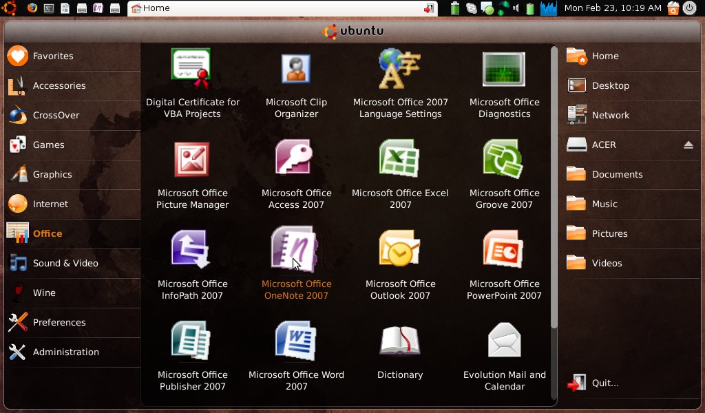
Netbook Remix with MS Office
Awesome things:
The netbook launcher is probably the best part of this entire package. It works well, looks nice, and doesn't use very many cpu cycles. The framework they used on this (clutter) really has potential in my opinion and if they keep developing applications for gnome with this framework it will probably become the desktop of choice for ease of use alone.
The app switcher with maximus is probably the second best part simply because it takes advantage of the smaller screen resolution. I originally thought that it would be annoying to have just the icon to tell me what the program was, but it really isn't nearly as bad as I thought it would be. It is pretty easy to remember where the icon for the particular window is. Another plus is the fact that the titlebars will take up as much space as possible. Even with long window names (movies on Tudou...looong names) I have not yet managed to get the ... to show up in the title bar.
Not so awesome things:
There isn't very many things I can really see wrong with this except for one bug in the netbook-remix launcher. Whenever something changes in the menus the launcher will close and not reopen until I restart it using alt-f2. However, since the last update this hasn't happened so they might have fixed it.
Microsoft Office:
The screenshot above shows my Microsoft Office installation. This took two-ish days to get working. For the longest time I was trying to use WINE to install it, but to no avail. The rpcrt4 dll would never replace properly and the whole thing would hang up on pipe_wait status with a fatal dll error. I eventually decided to use crossover linux and install it that way. It installed on the first try within 45 minutes. So far the only problem I am having with it is microsoft word crashing when it starts up. This isn't too much of a problem because I only plan on using OneNote on Ubuntu and switching into windows to write papers and stuff if I need to on this computer (I would prefer to use my larger computer for those).
Not so temporary...
Well I have decided to place my actual website on this server. My home server has failed due to router issues and I will probably be redesigning the entire website in the near future anyway since it uses outdated layout techniques. This server is basically the smith-marsden.org website that I work on for my dad's side of the family. I plan on downloading the contents of my server to here over the weekend so that I can try to clean things up a bit and hopefully get this site back on the map.
I will probably post progress on the new smith-marsden site here since that is currently my main development challenge.
Additional features of the new smith-marsden site:
- Ability to invite other users given to everyone
- RSS feeds on letter submissions
- More information stored so that it is all in one place that is private rather than facebook or somethwere else which could be quite public
- New state of the art layout techniques enhance the website
- AJAX allows pages to submit forms without reloading, making page load times faster and looks really cool.
- The entire thing is made using CakePHP, a robust framework.
- More to come as I think of them and make them...
Recent posts
Search through tags with mini.pick in neovimWriting reusable USB device descriptors (and other constant data) with C++ constexpr
Using "access" types and "new" in VHDL
A New Blog
A good workflow and build system with OpenSCAD and Makefiles