Kevin Cuzner's Personal Blog
Electronics, Embedded Systems, and Software are my breakfast, lunch, and dinner.
Building a USB bootloader for an STM32
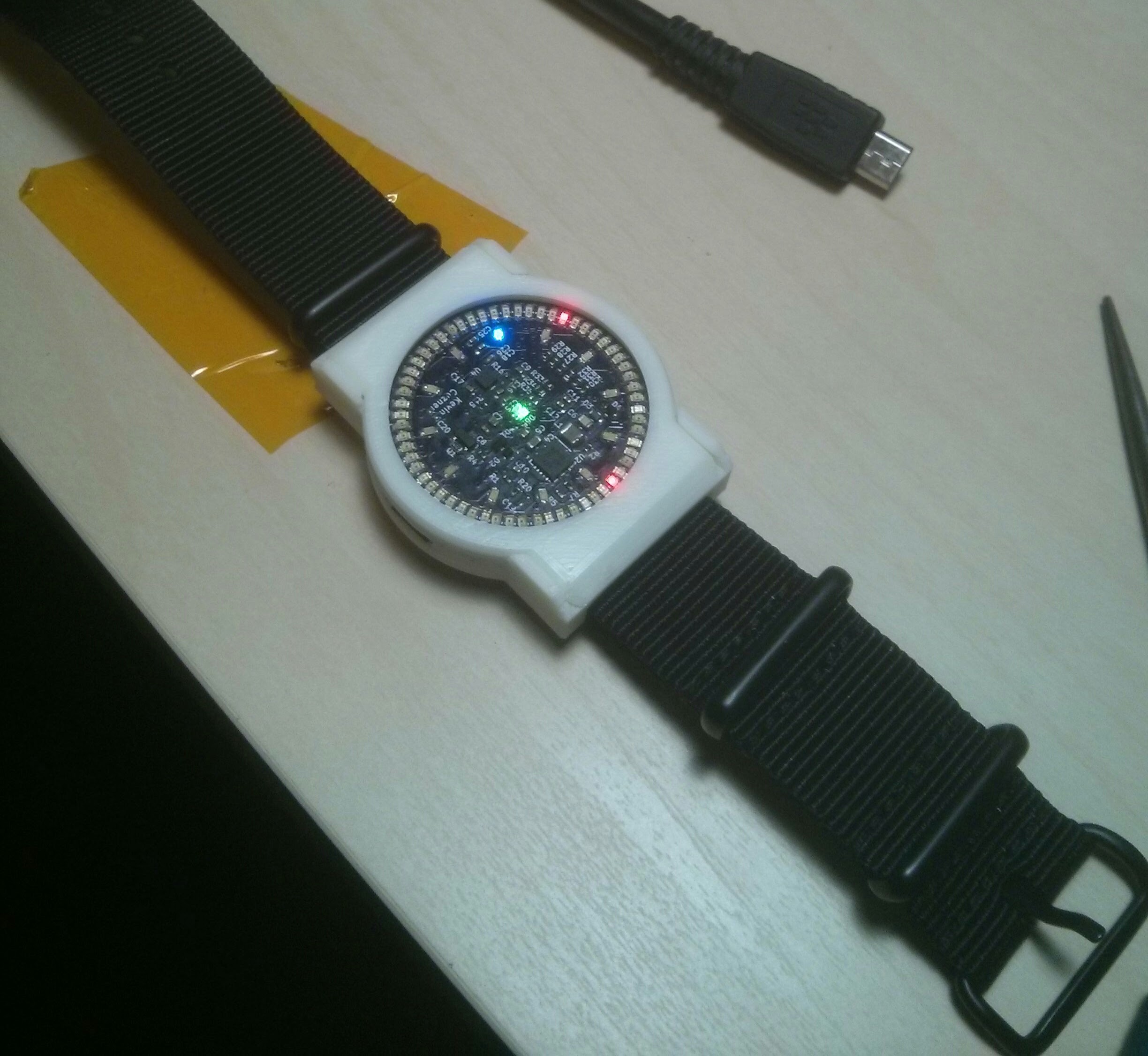
As my final installment for the posts about my LED Wristwatch project I wanted to write about the self-programming bootloader I made for an STM32L052 and describe how it works. So far it has shown itself to be fairly robust and I haven't had to get out my STLink to reprogram the watch for quite some time.
The main object of this bootloader is to facilitate reprogramming of the device without requiring a external programmer. There are two ways that a microcontroller can accomplish this generally:
- Include a binary image in every compiled program that is copied into RAM and runs a bootloader program that allows for self-reprogramming.
- Reserve a section of flash for a bootloader that can reprogram the rest of flash.
Each of these ways has their pros and cons. Option 1 allows for the user program to use all available flash (aside from the blob size and bootstrapping code). It also might not require a relocatable interrupt vector table (something that some ARM Cortex microcontrollers lack). However, it also means that there is no recovery without using JTAG or SWD to reflash the microcontroller if you somehow mess up the switchover into the bootloader. Option 2 allows for a fairly fail-safe bootloader. The bootloader is always there, even if the user program is not working right. So long as the device provides a hardware method for entering bootloader mode, the device can always be recovered. However, Option 2 is difficult to update (you have to flash it with a special program that overwrites the bootloader), wastes unused space in the bootloader-reserved section, and also requires some features that not all microcontrollers have.
Because the STM32L052 has a large amount of flash (64K) and implements the vector-table-offset register (allowing the interrupt vector table to be relocated), I decided to go with Option 2. Example code for this post can be found here:
**https://github.com/kcuzner/led-watch**
Contents
Cross-platform driverless USB: The Human Interface Device
During my LED Wristwatch project, I decided early on that I wanted to do something different with the way my USB stuff was implemented. In the past, I have almost exclusively used libusb to talk to my devices in terms of raw bulk packets or raw setup requests. While this is ok, it isn't quite as easy to do once you cross out of the fruited plains of Linux-land into the barren desert of Windows. This project instead made the watch identify itself (enumerate) as a USB Human Interface Device (HID).
What I would like to do in this post is a step-by-step tutorial for modifying a USB device to enumerate as a human interface device. I'll start with an overview of HID, then move on to modifying the USB descriptors and setting up your device endpoints so that it sends reports, followed by a few notes on writing host software for Windows and Linux that communicates to devices using raw reports. With a little bit of work, you should be able to replace many things done exclusively with libusb with a cross-platform system that requires no drivers. Example code for this post can be found here:
**https://github.com/kcuzner/led-watch**
One thing to note is that since I'm using my LED Watch as an example, I'm going to be extending using my API, which I describe a little bit here. The main source code files for this can be found in common/src/usb.c and common/src/usb_hid.c.
Contents
Bare metal STM32: Writing a USB driver
A couple years ago I wrote a post about writing a bare metal USB driver for the Teensy 3.1, which uses Freescale Kinetis K20 microcontroller. Over the past couple years I've switched over to instead using the STM32 series of microcontrollers since they are cheaper to program the "right" way (the dirt-cheap STLink v2 enables that). I almost always prefer to use the microcontroller IC by itself, rather than building around a development kit since I find that to be much more interesting.

One of my recent (or not so recent) projects was an LED Wristwatch which utilized an STM32L052. This microcontroller is optimized for low power, but contains a USB peripheral which I used for talking to the wristwatch from my PC, both for setting the time and for reflashing the firmware. This was one of my first hobby projects where I designed something without any prior breadboarding (beyond the battery charger circuit). The USB and such was all rather "cross your fingers and hope it works" and it just so happened to work without a problem.
In this post I'm going to only cover a small portion of what I learned from the USB portion of the watch. There will be a further followup on making the watch show up as a HID Device and writing a USB bootloader.
Example code for this post can be found here:
**https://github.com/kcuzner/led-watch**
(mainly in common/src/usb.c and common/include/usb.h)
My objective here is to walk quickly through the operation of the USB Peripheral, specifically the Packet Memory Area, then talk a bit about how the USB Peripheral does transfers, and move on to how I structured my code to abstract the USB packetizing logic away from the application.
Recent posts
Search through tags with mini.pick in neovimWriting reusable USB device descriptors (and other constant data) with C++ constexpr
Using "access" types and "new" in VHDL
A New Blog
A good workflow and build system with OpenSCAD and Makefiles