Kevin Cuzner's Personal Blog
Electronics, Embedded Systems, and Software are my breakfast, lunch, and dinner.
Modifying my computer case
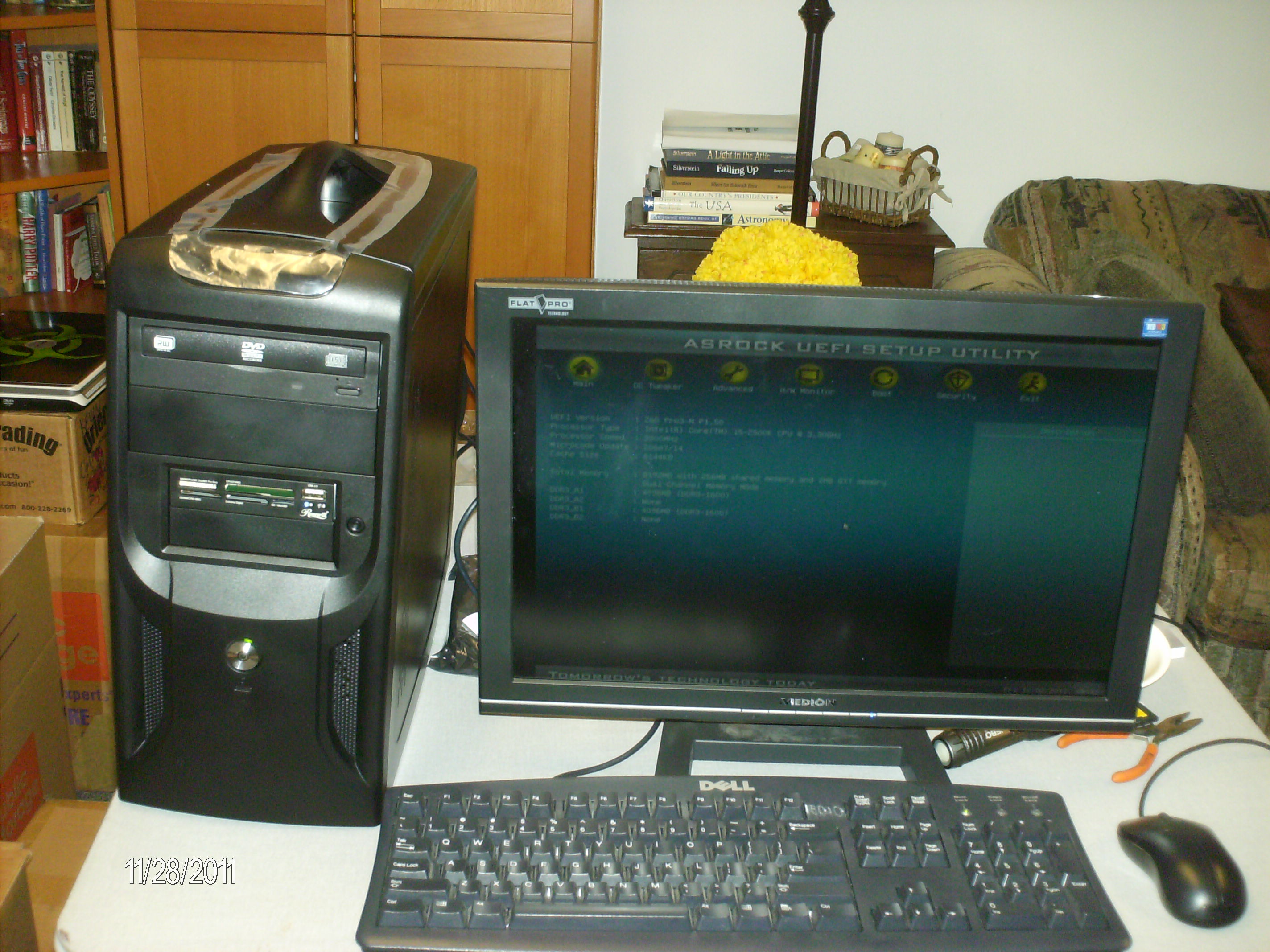
The computer
In November I purchased the parts for a new computer since mine was getting very old (I got it in 2006 and even then it wasn't exactly top of the line). I put it together and it has been performing admirably for a couple months now. I was researching graphics cards and it occurred to me that I would have to move my hard drive up a slot to fit a large graphics card in my case.
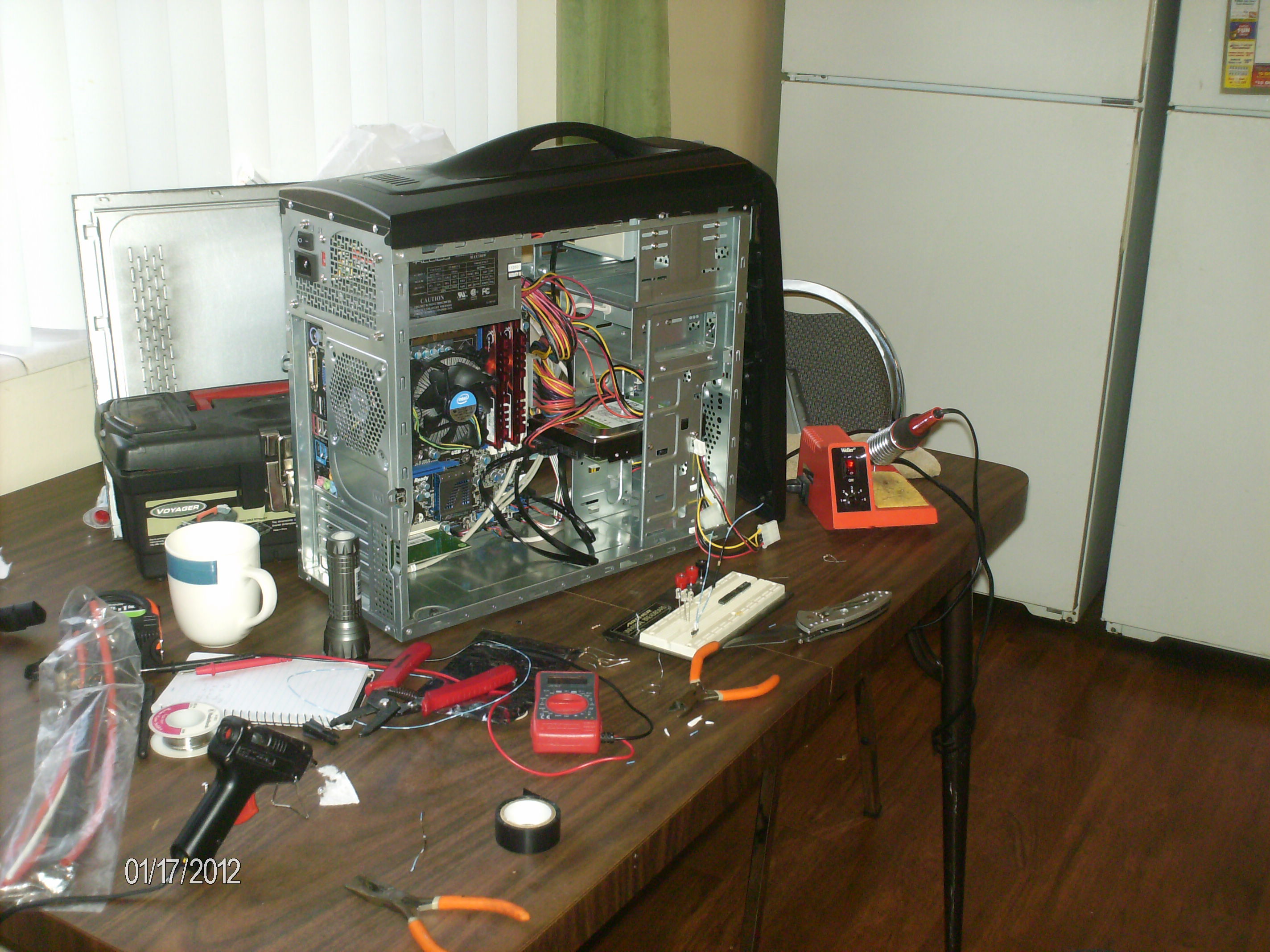
After moving stuff around inside
So, I opened the case and started moving stuff around. I also decided to re-organize the cables so that they wouldn't be dangling precariously above the CPU fan by stuffing them behind the HDD cage. During that process I took some strain off the SATA cables (they are kind of stiff and I think they were putting undue stress on the sockets on the motherboard, so I moved them around so that they wouldn't be so convoluted). After finishing all this it occurred to me that my case would look sweet if I were to add some LEDs to it. I then set out to install some LEDs.
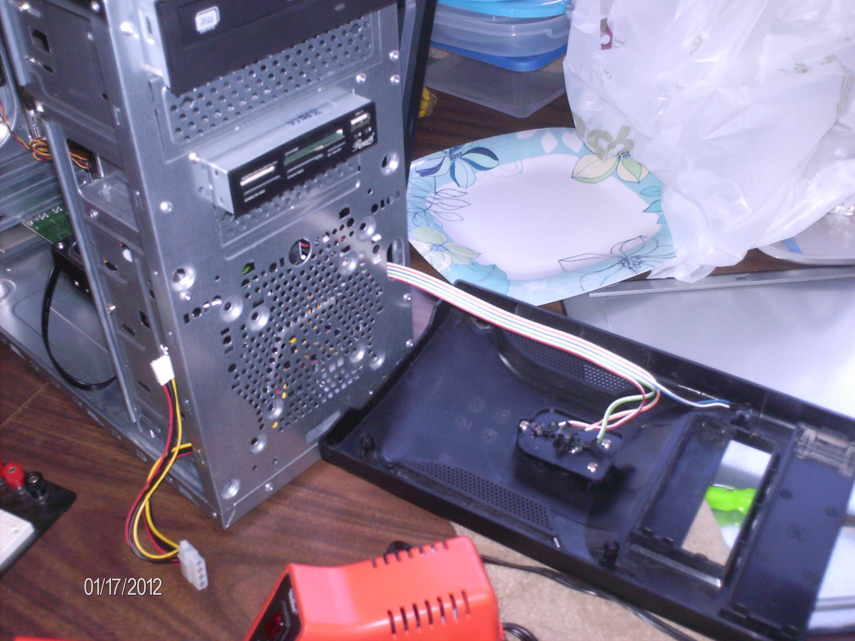
The grille and power connector
In the front of the case there is a plastic piece that covers the metal body of the case and also holds the power button, reset button, and HDD light. This case has a grille on it to allow air to pass through into the front fan (if I had one installed).
I decided that this grille could look awesome if it had some backlighting. I had considered using a lighted fan for this purpose before, but since fans are mounted on the inside of the case it would project the shadows from the internal metal structure onto the plastic grille, ruining the effect. I decided to mount some white LEDs on the inside of the plastic piece pointing towards the inside of the case so they could shine on and illuminate the part behind the grille to give a "glowing" effect. Here is what I used:
- Some spare really thick black matte cardstock my sister let me have (she is into artsy things)
- 4 White LEDs that I had lying around
- A 15Ω resistor to limit the current (4 LEDs @ 25mA each comes to 100mA at a voltage drop of 3.5V)
- A .1" header I had in a parts box
- Some wire
- Some tape
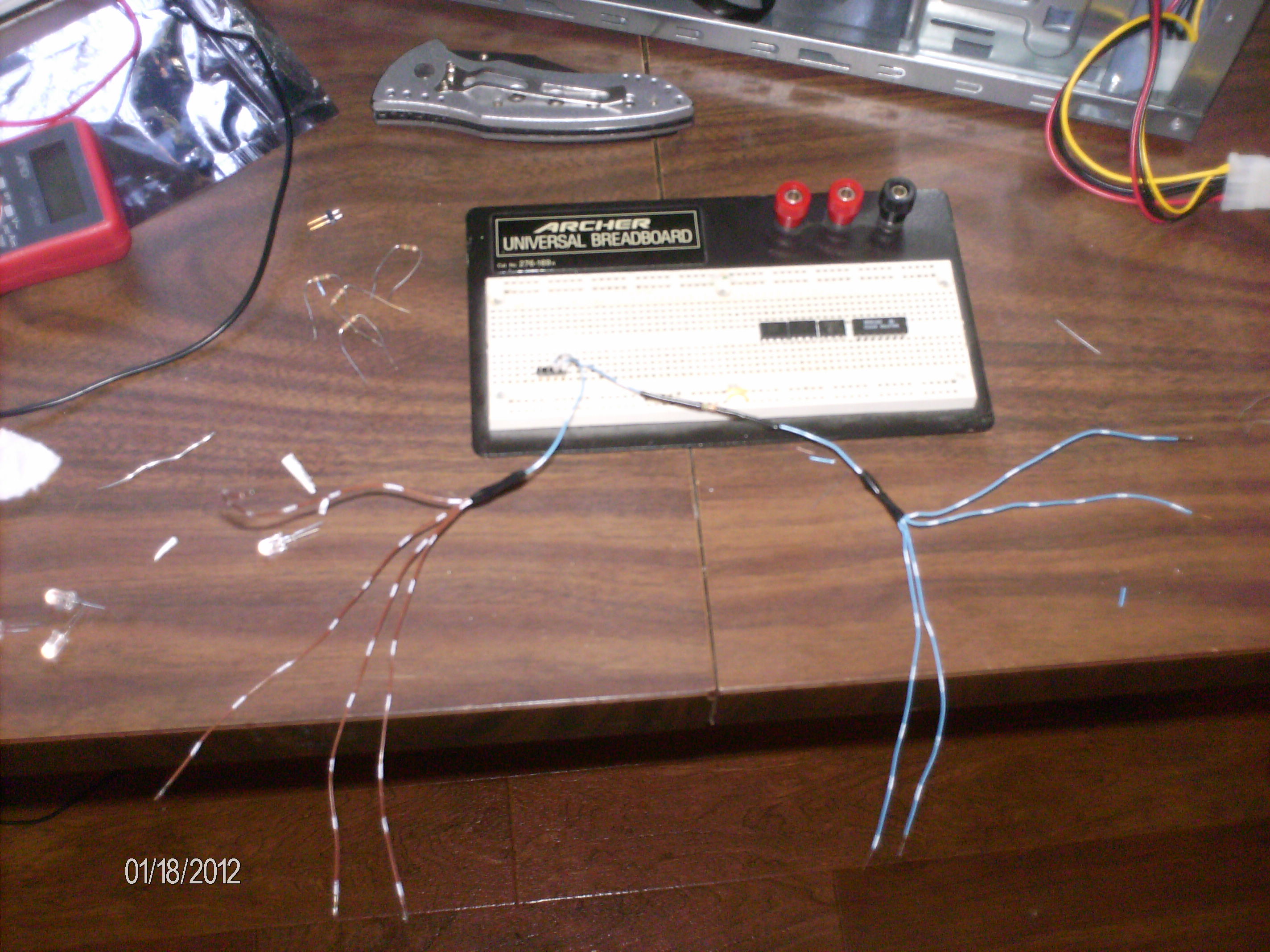
The spider wires
I started out by soldering the header to some wires to take the 5V and GND line off of the small .1" power connector in my computer. I then put the resistor on the positive rail and then split everything off into 4 wires (8 in total: 4 power, 4 ground). The result looked rather like a spider in my opinion. After that it was a relatively simple job of soldering the long lead of the LEDs to the positive rail and the other side to the negative rail. Thus, the LED assembly was completed.
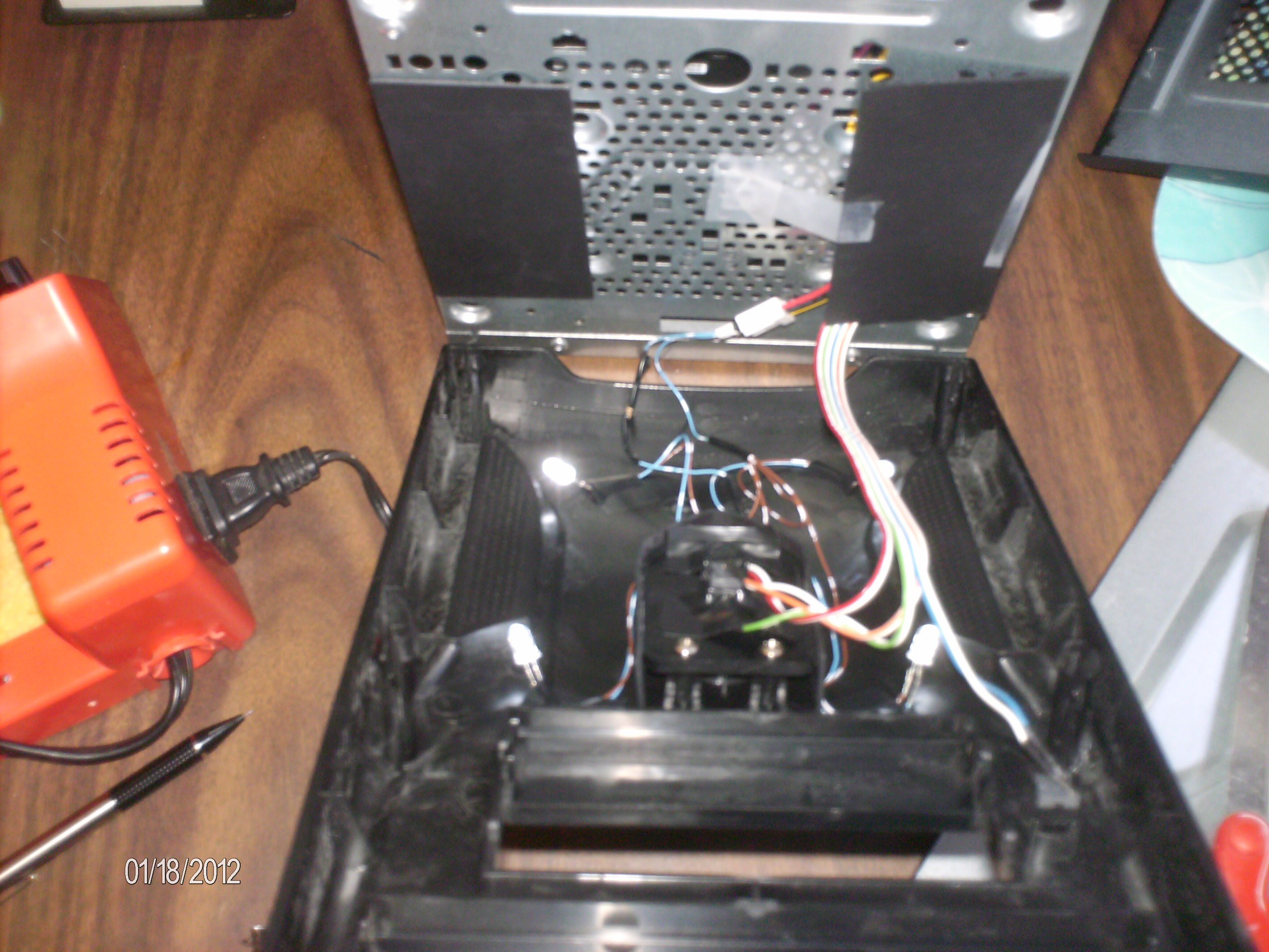
Matte board and aimed LEDs
The more difficult part was attaching the matte board to the metal part of the case and then aiming the LEDs. The matte board was necessary because without it the LEDs reflected a little too well off the metal of the case and they could be clearly seen through the grille. I cut the matte board into two pieces large enough to cover the metal on either side of the grille and used tape to hold it in place. One hitch came up with the wires going to the front of the case: the hole for the wires was right beneath one of the grilles and was not easily covered by the cardstock. I ended up just basically laying the cardstock over the hole and wires and moving them around so as to not be visible through the grille. The next bit of matte board I used was to create a shroud of sorts around the HDD and power lights since the LEDs were bright enough that they shined through the bezels for those lights as well. I then spent a while aiming the lights until I was satisfied and then I put the computer back together so I could enjoy my new lights.
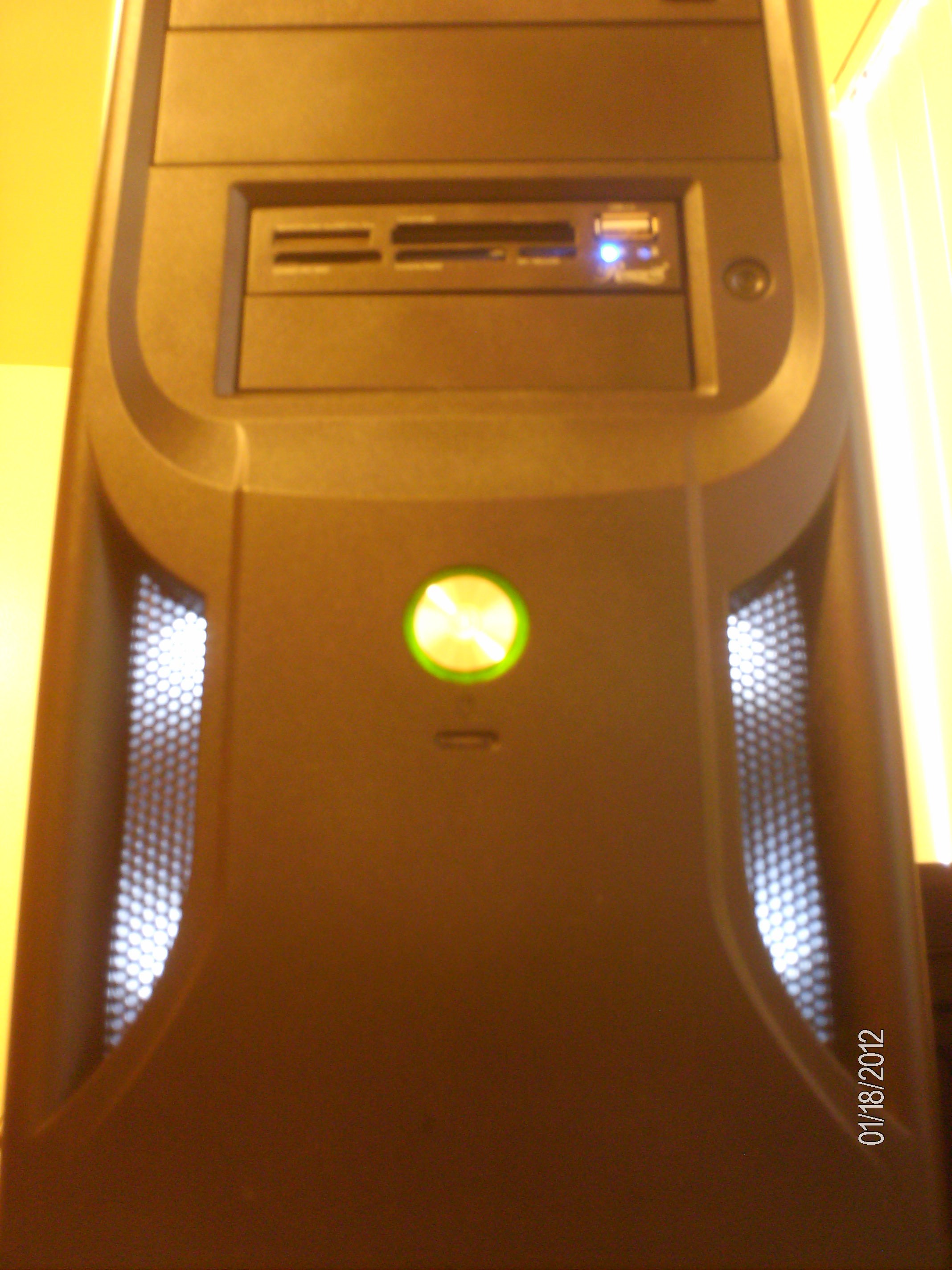
The Final Effect
All in all my specs are as follows:
- ASRock Z68 Pro3-M Motherboard (microATX)
- Intel Core i5-2500K Processor running at the stock frequency
- 8GB G.Skill Ripjaws DDR3 RAM
- 1TB Western Digital Green HD (using wdantiparkd to counter the head parking issues)
- Rosewill RNX-N300X Wireless b/g/n card
- Apex 500W Power Supply
- Cheap DVD burner
- Cheap Rosewill card reader
- Apex microATX case with a handle (best feature!) and some LEDs
- Ubuntu 11.10 64-bit for an OS
A followup on the Dot Matrix Clock
Since I never quite finished the story about my dot matrix clock, I see no reason why I shouldn't write a bit of a continuation of my current developments. Shortly before I left on my mission for my church in November 2009, I received my boards for the dot matrix clock and assembled them. However, I ran into a problem: The displays would turn off after the voltages on the gates of the row driving mosfets reached a certain voltage and when the voltage was at a level where it would turn on the display, it had some problems with turning on and off the LEDs. Now, after I left on my mission I would think about this once in a while and I figured out the problem: I was using N-Channel mosfets with only 5V or less of gate driving voltage so they wouldn't turn on/off all the way. I am sure there are more problems than just that, but I keep kicking myself for using N-Channel mosfets instead of using P-Channel. Had I used P-Channel, the problem would have been avoided and this whole thing would have worked great. For the moment, however, this project is on hold since I am designing and building a few things that I will need in the long term here at college since I can't lug around a power supply and an oscilloscope.
So, in summary, if I were to do a re-design I would change the following:
- The row drivers would be P-Channel mosfets. This would require using something other than a 4->16 demux for a gate driver unless I could find one with inverted outputs. Even with that I would probably put some very small gate drivers (if they exist...the size restriction might be too much) as a buffer to ensure the mosfets were turning on and off properly.
- I would factor in larger tolerances. If there was one design lesson I learned from getting these boards it is that I need to make sure that I make the holes for things a little larger. It would definitely make assembly easier.
- The PIC18F4550 would be replaced for a ATMega of some sort or maybe even a small FPGA. I was running into speed problems with the 18F4550 with getting refresh rates up (I know this is contrary to previous posts, but I was starting to have problems getting 30-60fps like I wanted...even though the image wasn't showing up anyway because of the mosfets). The 12MIPS speed was just a tad too slow and so I think if I were to use a 20MIPS ATMega it would work a lot better. Also, the tools for ATMega seem to be a little more opensourced than the ones for the PIC. I say this because avrgcc runs much better on my Linux machines than the various C compilers for the PIC series. Also, my AVR programmer (a USBASP) has very good native Linux support.
Now all that is left for me to do is to figure out how I can modify the boards I have so that I wouldn't have to drop $70 again...
Back again
After serving a two year mission for my church, I have returned! While on my mission I didn't have much chance to work on my various projects, but I sure thought a lot and wrote down a lot. I also managed to build some pretty interesting things (OK...maybe not that interesting).
On the mission, my two most interesting things I built were a small coilgun (also called a gauss gun) and some large headphones for a deaf lady. I had the most fun with the coilgun since it required the most effort on my part to create. It is housed in the case of a broken airsoft gun and is powered by a camera flash charger and two camera flash capacitors.
The Coilgun

The Coilgun without it's case
The coilgun is constructed of a relatively simple circuit which draws power for a camera flash charger from a AA battery (housed in what was the magazine for the airsoft gun) connected to two photo flash capacitors. There is an SCR connected in series with the coil (the green thing) which use the capacitors as a power source. The trigger uses very tiny snap action limit switch (it was the smallest I could find at a reasonable price) to trigger the SCR (through a 20K resistor). The total cost for parts was $10 since the case was free and the camera flashes were free. The working voltage is about 330V or so which is normal for photo chargers, but when building it I managed only to shock myself once.

Coilgun with the case screwed on
It shoots nails or anything else magnetic cut to a specific length so they are just a little inside the coil. The gun doesn't have much power (I would more call it a "nail tosser" than a gun), but it is fun to use because of the high pitched charging sound makes the gun sound bigger than it actually is (more bark than bite you could say).

Coilgun with the coil exposed
There is a 1000V diode in reverse across the coil to prevent damage to the SCR and also a 1MΩ resistor across the capacitors so that they don't retain charge for years and shock some unsuspecting person wondering what is inside this strange looking gun. I have had great fun with this project and someday I hope to build a much larger multi-stage one. Of course, lack of funds will keep that one out of reach for a little while at least, but it is something to work towards.
The Headphones

The Headphones with the ear pads rubber banded on
In one of the apartments I lived in I was with some other missionaries who served a deaf congregation. Their ASL teacher was mostly deaf (she had 1% hearing in one of her ears) and so she could listen to music occasionally. She was using some high quality DJ headphones to do this since she had to turn the music up really really loud for her to be able to hear it. Sadly, she let a friend borrow them and they got broken. So, one of the other missionaries who also enjoyed building things volunteered him and myself to construct new headphones for her. He built the case and I did the electronics. Electronically, it was a simple project since it was just taking a cheap iPod stereo and extending the wires out to fit into the case in the shape of headphones.

The completed headphones
The basic design was to use a hamster ball cut in half with coat wire bridging the two speakers. Socks sewed onto cardboard with a cotton filling would be used for the ear pads. An old belt would serve as a size adjuster. The headphones actually turned out pretty nice and were very loud and had pretty good sound quality considering that they were made out of a really cheap iPod speaker set. The only problem was that when they were turned up high the quality would drop dramatically due to clipping/overloading/whatever you call that noise a stereo makes when its turned up to loud. She had to use them at that volume and while she was able to hear the music she asked 'what is that strange noise on top of the music?' and so they ended up being returned and the missionary who built the case bought the cost of the electronics from me and he used the headphones after that.
I have also had many ideas relating to future projects which I will post here when I am ready. Within my first few weeks back I constructed a new computer which should help me out and I hope for it to last at least 5-7 years. I will be posting about that soon as well.
Dot Matrix Clock: Display board assembly
Well, here it is. The moment I have been anticipating for a good while: The boards came in and I assembled them. I made a few videos and took a few pictures. I won't post the videos yet since I am still going through them and making sure that I don't go and make a fool of myself.
After getting that far, I believe my camera died. Anyways, I assembled the breakout board and completed all the parts of the display. I did not solder down all the display modules to the pcb because I am going to be fiddling around with the resistors on the column sinks and I didn't want to have to desolder a display before being able to do anything else. The next day, I started testing:
As for testing and stuff, it mostly works. I made a few errors in both the hardware and the software, but I at least got the LEDs to turn on (I have not, however, gotten them to turn off properly...). My original program which should have been immediately portable to the hardware did not work so well and I ended up writing the entire display portion of the program in assembler: Apparently doing a variable bit shift on a 32 bit number takes up a very...long...time when compiled in C for the PIC18F. The main issue with the original program was that when I expanded the display size to 40x16 it suddenly had no refresh rate to speak of. This was mainly a product of the way I had organized memory. I had stuck the entire display into an array of long ints so that access to individual pixels could be done almost entirely by index. Sadly, when the size of the display was multiplied by 10 the computation of the bitmask began to take too long and made it impossible to properly refresh the rows. The assembly program I made to replace this organizes memory in the same fashion that I believe VGA cards organize the memory: Everything in one big long array which has no end-of-row designation and just wraps around when it is displayed. This ended up being much faster and hopefully it will work for the finished product.
As for the hardware problems, I have several. First of all, I made the primary mechanical engineering mestake when designing the package footprints: I didn't factor in tolerances. All the through-hole parts BARELY fit. In fact, I have to coax everything in using a craft knife to get the pins lined up exactly before the part will even go in. The button pins are going to have to be sanded down since there is a taper to the pins that was not in the datasheet which makes the pins too large for the holes. The next big problem is that the column sinks are behaving very strangely. After the voltage into the LEDs passes above 3.3V or so some of the columns just stop sinking while others stay on. I have a few ideas to find out exactly what is going on here, but I have no real plan of action to fix that as of yet. My final problem is that I somehow managed to lift a pad when soldering down a resistor. How this happened I am not sure, but I think it has to do with cheap board construction and using a solder wik that is too big. I barely managed to find a trace to solder to, so it is kind of fragile even with the hot glue I used to secure the wirewrapping wire I used as a trace extender. The next time I do this I am putting a via in EVERY trace that runs into a pad, even if it doesn't need one just for this sort of situation.
Anyway, aside from the mentioned problems the boards turned out pretty well. Olimex was fast and relatively polite. Their construction wasn't too bad (aside from the pad, but that may have been mostly my fault) and the boards shipped right on time and arrived right on time (to the day, in fact). Overall I would say this whole board experience wasn't bad and since it mostly worked I will say I didn't waste my money.
New Host!
Thanks to my friend Walter Zarnoch, I now have a hosting plan that will work for the next two years while I am gone on a mission for my church. The plan is to basically keep my site up here while I am gone, hopefully getting hits and such from people interested in the crap on here, and then work on it after I get back. As for the future, I might keep this arrangement, but for all I know I might find out about a better arrangement later. Right now we share a hosting plan, splitting the cost 50/50, so its really not too bad at all costwise for a site I won't really be touching for two years.
Anyway, hopefully this works out...and I am sure glad to be off my grandma's website's host.
Dot Matrix Clock: Renderings of the display board
I finished modeling the entire board in blender today, so here are a few different views of the clock:
I created these images in blender by exporting images of the various pcb layers from eagle, compositing them in gimp into front and back images, and uv-ing then onto the board. All the components were done by looking at their datasheets of course.
Dot Matrix Clock: Open sourcing the display schematic
Following the suggestion of a friend, I am going to open source a portion of the software (when it comes) and the display schematic. After I get the board and finish up the software I plan on releasing this as a kit. So far it is looking like the kit is going to cost somewhere between $110-$140. I would supply the board with the controller already soldered and programmed.
As it stands, the hardware features are as follows:
- 40x16 display with two LEDs per pixel giving 1280 LEDs
- Constant Current LED sink chips to prevent varying brightness problems with the display.
- PIC18F4550 Microcontroller running off the PLL on a 16Mhz oscillator giving 12MIPS throughput
- 41-pin high density board to board connector. A breakout board is included since development without one would be nearly impossible.
- 4 buttons. These are not connected to the display microcontroller, but can be read through the board to board connector.
- 8-bit parallel bus with CS, R/W, and CLK pins for communicating with the microcontroller in the fastest way possible. I have not yet decided on a maximum clock speed, but the clock is on an interrupt enabled pin.
The planned basic software features are as follows:
- Built in font(s). These would not be restricted by rows or columns and would be placeable by specifying start coordinates. I may also add the ability to have either user fonts and/or variable width characters.
- Pixel-by-pixel control of graphics. Each dot has 16 possible colors (4 brightness levels per color in each pixel...two colors). This would also allow direct memory "dumps" into the display for the possibility of animated things (assuming you have a powerful enough processor on the master side of the bus).
- Triple buffering to prevent overwriting the buffer currently being displayed. This may be extended to allow animations by switching buffers, but I am not sure if I have enough memory yet.
- At least 15fps throughput. 30fps is my target.
- Bootloadable using only bus commands, no POR required. I may or may not make the bootloader protocol public, but I am leaning toward making it public.
- More to come if I accomplish these and still have some clock ticks left over...
As for the board gerbers, I am going to keep them to myself. I spent nearly a year on the board design and I think I need to have at least some profit come of it before I release it to the world for some crazy board outsourcer to steal and clone at half the price I managed to get it fabbed at. I'll tell you this much: Eagle's autorouter can't handle the entire thing and there are well over 300 nets (not airwires...nets), so good luck.
Now for the schematic. Here you go:

Dot Matrix Display Schematic v. 3.5
Now, before someone goes on yelling about how much the BSS138 sucks as a MOSFET I guess I should say that I have replaced it with a much better one that can actually source the current I need it to. The BSS138 has a couple ohms of RdsOn, so I replaced it with a MOSFET that has around 0.25Ω RdsOn. Enjoy.
Dot Matrix Clock: Order placed
I have finally placed my order for the dot matrix clock. I chose revision 3.5 which had a surface mount crystal instead of the through hole version.
The only problem I have run into so far is that Olimex requires that the payment informatoin be faxed, so I have to use the fax machine at work to fax the order information. Luckily, my dad also works there and if he uses it for personal use there is much less chance of him being punished than me.
I just have to hope that they notice that all my solder side stuff is mirrored as that is the default with Eagle.
Dot Matrix Clock: Down to two candidates
- Well, just a short update here. I think I will probably be at home for another month or so, so I am going to go ahead and order the dot matrix clock display board. However, I need to decide between a surface mount crystal or a through hole crystal. I think my post on edaboard.com pretty much sums up my dilemma:
I have two possible versions I have been designing for some time now. Since it is looking like I am going to be home long enough to finish it I guess I should get it fabricated. However, one thing needs to be decided before I order it and that is whether or not I should use a Through-Hole or Surface Mount crystal.
Originally I was going to just use a through hole crystal, but after having a friend of mine look over the board as another set of eyes he pointed out that my crystal traces were over 3in long and had several vias in them. So, we identified a spot where a surface mount crystal could go with no vias and 0.5" traces. The criteria for fitting in this space was that the crystal had to be no more than 7mm long, 3mm wide, and 1.5mm tall. The obvious problem here is that nothing really fit in that space except for a crystal made by Abracon that is 3.2x2.5x0.7mm. Now the problem is size: is the crystal too small?
My resources: 0.015" solder, 1/32" spade tip (on a variable temperature soldering iron), solder wick, and a relatively steady hand (successfully soldered a .4mm pitch 64tqfp by hand without overheating it). Things I don't have: A magnifier, reflow oven Things I don't have but could get: Heat gun, solder paste
I don't have enough experience with this sort of thing to answer it myself and I really can't afford to buy two versions of this board. Is using a crystal this small really worth it?
Well, hopefully I will have that problem solved before the end of the month so I can place my order as soon as Olimex comes out of their summer break (for some reason, Europeans take a month long vacation from work in the summer...how odd...).
What is this with premade stuff??
I was recently talking to a friend online after conferring with him about my dot matrix clock circuit board layout (now to rev. 3.4) when he mentioned that all people have to do nowadays to become a hardware "hacker" is to go buy an premade Arduino kit, attach it to some other premade piece of hardware, and load a premade program into it. More and more I have noticed this to be true. People no longer design and program their own stuff; they just buy something and say they hacked it together. Although I think having a standardized hardware to work with for embedded stuff like what I mainly do would be nice, I don't see the fun in assembling and programming somebody else's code into somebody else's device. What is the novelty in that? Where is the learning?
Even with this trend I have seen a few other examples of people coming up with something cool using premade hardware. A good example is from my History of Creativity class I took my first two semesters at BYU. At the end of each semester each student had to create and present a "creativity project" which showed creativity at some level and related it to the class. My second semester, one person in the class made something that absolutely astounded me in its simplicity and how obvious it was to construct. He basically made a multitouch enabled touch screen using an LCD with the backing taken off, a bunch of infrared LEDs shining into a glass plate, and a camera with a remote control bezel over the lens. He hooked up the webcam to the computer and used open source software to interface it to his computer as a multitouch human interface device (HID). He said it cost him about $200 mainly because of the monitor he bought and cannibalized. I was impressed. I was so surprised I hadn't thought of doing something like that. It's things like that with premade stuff that I find awesome. I had never before seen a monitor like this and from what he said it was the cheapest yet from a quick look around on the web.
Now why would it bug me that people are using so much premade stuff? Well, it puts people like me who design their own custom boards and software without using very many ready made libraries or a premade circuit layout into the shadows. It really does. When I say something like "I built this...take a look..." people then ask "Oh, where did you buy that?" I never buy stuff and say I built it. I believe the only kit I have ever purchased was a solar racer from solarbotics when I was younger. Other than that everything I have made was from my own self. The only time I buy something is because I can't make it for cheaper. People buying all this premade stuff kind of dulls the novelty of people using "custom" hardware on computers and the like. Its like what happened to CB radios: When everyone was on clogging up the channels the novelty was lost. Although I have never been into CB radios, I can see the point of that. Something is novel because its something few people do. When I first started with microcontrollers in 2005, very very few people I knew had experience with them. Now, its like everyone is buying their Arduino's and sumo bot boards, programming them with some premade software, and setting them loose as their own creation. Of course, there are the people who go buy these things but then make up their own projects with them. I happen to know one person who has a sumobot that he made from premade boards that he installed a webcam on, programmed some interface software, and now has a person (or rather, bright colored object) seeking robot.
The only way in my mind that people redeem themselves from falling into the bandwagon of buy it yourself fake hacker stuff is by expanding it to fill another need. Innovation is what drives the world nowadays, not invention. The only people who can invent things now are people with clean rooms and lots of money. Since there aren't many of those people in the world, the vast majority of us "normal" people have to suffice for innovation. Being in the United States, I would mainly refer to improving American innovation so that I can live in a country that has cooler innovations than other countries, but since the internet is a global audience its better to say that the world should be more innovative.
Recent posts
Search through tags with mini.pick in neovimWriting reusable USB device descriptors (and other constant data) with C++ constexpr
Using "access" types and "new" in VHDL
A New Blog
A good workflow and build system with OpenSCAD and Makefiles