Kevin Cuzner's Personal Blog
Electronics, Embedded Systems, and Software are my breakfast, lunch, and dinner.
Ghetto Chronometer
Jun 27, 2009
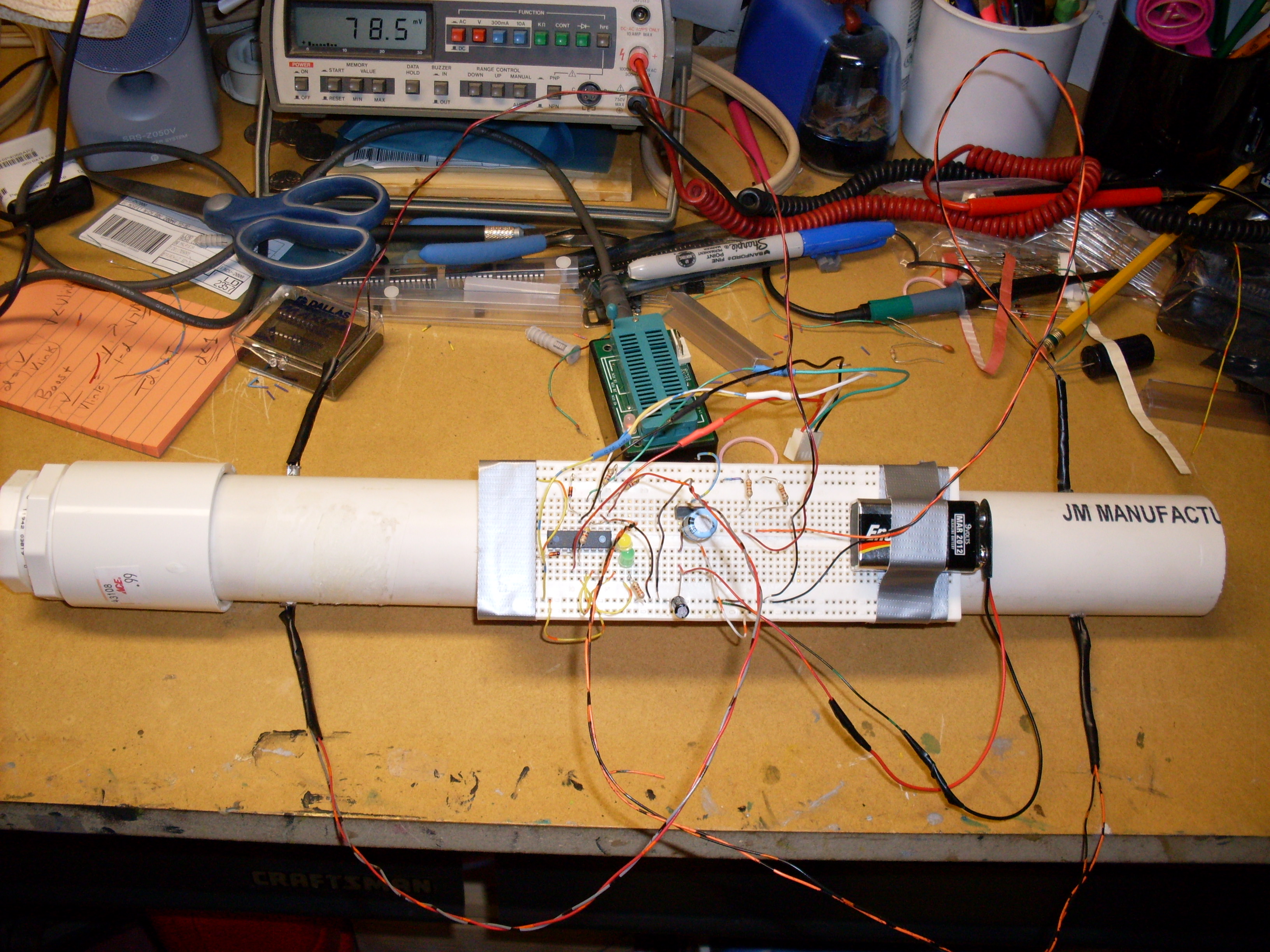
For once, I did something simple. I have always wanted to know how fast my potato gun shoots and I have also known how to find out, but I had never gotten around to actually building something to measure the speed of a moving object. I built this almost completely out of parts that are available at your local radio shack and hardware stores. The device consists of a 2" PVC pipe with two sets of infrared diodes/detectors placed in holes spaced a foot apart which are connected to a PIC microcontroller that I have programmed to act as a "stopwatch" measuring in microseconds. Once a time is captured, the value is written to EEPROM for later gathering at the computer.

The Ghetto Chronometer. It looks rather like a pipe bomb doesn't it?
Parts List
I noticed while building this that I was using parts that were originally purchased on radioshack (aside from the microcontroller) and the home depot/ace hardware. Here is the list of parts with a few prices:
- Infrared Emitter/Detector sets ($3.49, radioshack)
- 330Ω 1/4W resistors ( $0.02 apiece if you get the 500 piece resistor set, otherwise $0.20 apiece in the 5-pack; radioshack). This value can be fudged just about anywhere as long as it doesn't drop below 90Ω or so. The lower the value, the more chance of breaking the infrared emitters. The higher the value, the less light the emitters give off (which increases the chance for noise). Use the values on the back of the package to calculate the exact resistor value if you want a fully bright light. I think about 37Ω or so will push 150mA through it with a ~3V drop.
- ~470Ω 1/4W resistor. This is for the yellow and green LEDs
- 5mm (T1-3/4) LEDs, yellow and green. These can be picked up at radio shack for various prices depending what package you get them in.
- solderless breadboard (what I used) or those grid pcbs (both at radioshack)
- 7805 (5V) Regulator ($1.59, radioshack)
- PIC16F628A or a BasicStamp. The Basic Stamp is available at radio shack for an exorbitant price, but the PIC can be purchased for about $3 at most parts suppliers (look on octopart.com for prices). The programmer is not included in this estimate, but I built the programmer described in the WinPic manual for less than $20 (google it). I currently use a K128 USB Programmer.
- 4.7K 1/4W resistors, same story as the 330Ω except you shouldn't adjust this one.
- >=100uF, <=500uF capacitors (radioshack again, not sure on price...depends what you get)
- 9V battery clip (radio shack. price depends on the type)
- 9V battery
- 16" of PVC pipe 1/2" larger than your current barrel size (leaves clearence for the emitter/detectors)
- Enough bushings to get the above PVC down to your barrel size for attachment (mine took two...stupid hardware store)
- A PVC connector 1/2" larger than your current barrel size for connecting the device to the bushings
Instructions
These instructions assume enough knowledge to construct a circuit on a breadboard from a schematic along with enough mechanical skill to saw and drill stuff.
Attach (I would solder them, but you can twist and tape if you like) relatively long wires to the ends of each infrared emitter and detector. There should be two of each in total. Make the wires different colors per pin on each device so that they can be distinguished later. Make a note of where each wire went on the back of the package they came in which should have an internal diagram for each part if you got it at radio shack. Twist each pair of wires together so that each device has a long twisted pair of wires coming off of it.
Heatshrink or tape each lead coming off of the emitters and detectors individually and then per device. This is so that no short circuits happen and so that the device is easier to insert and remove from the PVC.

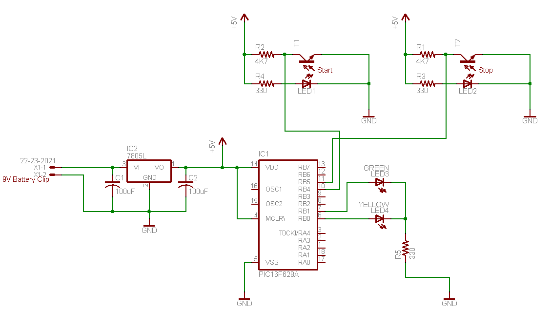
Chronometer Schematic
Assemble the circuit per the schematic. The schematic uses the PIC microcontroller, so it will have to be modified for a basic stamp.
If you used the PIC, program the microcontroller with fps.hex in this file. I have also included the assembly listing for anyone who is interested
In the 16" length of PVC, drill two sets of holes directly across from each other 2" from either end. They should end up a foot apart.
Attach the bushings and connector to the PVC. Which ever end you attach these to is called "start" in the schematic. The projectile (potato) should travel from "start" to "stop".
Duct tape what ever you assembled the circuit on to the PVC in the fasion shown in the picture of the device above.
Insert each emitter/detector set into the holes on the PVC. They should be lined up with an emitter on one side and a detector on the other. The potato will interrupt the beam of light going between the emitter and detector.
If the device is going to be used outside, it might be good to put duct tape or electrical tape over the ends of the emitters/detectors so that no light leaks into the 16" tube. Light leakage can cause considerable interference since the lights are not modulated in any way.
Load your potato gun.
Attach this to the end of your barrel and turn it on
Fire. The green LED should light up if it caught the speed correctly, the yellow one will light up if there was an error.
Read the microcontroller's EEPROM. The time it took in microseconds for the potato to go one foot should be written in locations 0x03 and 0x04, most significant byte first. Use a hex->decimal converter to get the value, multiply it by 0.000001, and take the inverse. This is the FPS of your gun. Subsequent firings will be written in locations 0x05 & 0x06, 0x07 & 0x08, and so on. It should remember where it was last written between runs until you reprogram it or run out of space.
How it works
Overall its pretty simple: A potato interrupts the "start" beam which starts the 16-bit timer and it interrupts the "stop" beam a few microseconds later which stops the 16-bit timer. After the timer is stopped, the value of the timer (which also happens to be the number of microseconds between the start and stop pulses) is written to the internal EEPROM at the address specified in location 0x00. The green LED is then turned on and the microcontroller wants for the next "start" interruption. If there is an error (like the EEPROM not being able to write or the timer overflowing), the yellow LED lights up and the microcontroller waits for the next start pulse.
The microcontroller runs on the internal oscillator which gives 1MIPS. The 16-bit timer is connected to the internal oscillator with no prescaler so that it increments every microsecond (1MIPS = 0.000001 per instruction) when the timer is turned on. Since it is a 16-bit timer, it can time a maximum of 65535 microseconds or 0.065535 seconds. This gives a minimum speed of 15.26fps and a maximum speed of 1,000,000fps. I guess this could be used on a rifle, but I am pretty sure the emitter/detector pairs would have to be switched out with something with less lag time.
To test to see if the infrared emitters are even working try looking at them through a digital camera. A digital camera has better eyes than we do, so it can see infrared as a whitish/purpleish light. The emitters are rather narrow beam, so they will have to be pointing right at the camera to be visible. Oh, and if any part of this heats up, thats bad. Nothing on this should generate much heat, including the regulator. The whole thing should draw about 50mA with the parts listed above.
Things to add
Obviously, there are some things that could be done with this to make it even cooler. Some of my ideas:
- Add an LCD screen that shows the milliseconds it took (or even fps)
- Store the value in feet per second instead of milliseconds. I would have done this in the first plac, but I don't feel like finding out how to do division like that in assembler.
- Add a serial interface so that it can hook up to a computer and report its findings. I was originally going to do this, but I didn't have enough 0.1uF capacitors for my MAX232 chip.
- Something to prevent the wires coming off of the emitters/detectors from getting bent if the gun roles around.
- ...
hardware programming
Recent posts
Using "access" types and "new" in VHDLA New Blog
A good workflow and build system with OpenSCAD and Makefiles
AVR TPI Programming With usbasp For Dummies
Writing reusable USB device descriptors with some XML, Python, and C